通过前面两篇教程文章的学习,相信大家对截门阀阀体的建模设计已经有了一定的掌握了,在本篇文章中,我们将向大家继续介绍,在完成阀体设计后,如何出整套完整的工程图,快一起来学习吧!
第一步:创建工程图
在右键菜单下进入2D工程图,创建A2工程图,比例为1:3,如图1所示。
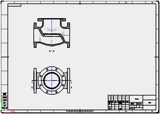
图1 创建A2工程图
第二步:创建投影视图
使用“布局”页面下的“投影”命令,创建投影视图,如图2所示。
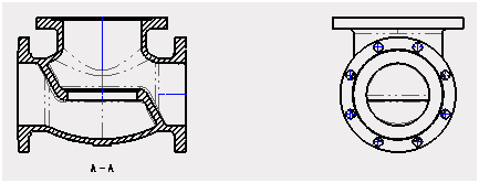
图2 投影视图
第三步:创建局部剖视图
使用“布局”页面下的“局部剖”命令,剖掉半边,深度为一半,如图3所示。
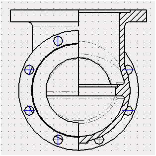
图3 局部剖视图
第四步:创建轴侧剖视图
使用“布局”页面下的“轴侧剖视图”命令,创建轴侧剖视图,如图4所示。
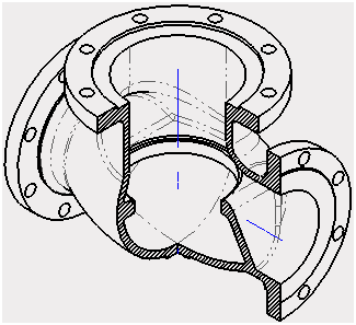
图4 轴侧剖视图
第五步:创建图层
使用“图层管理器”(图5)创建“视图”图层,把4个视图归属到这个图层中去。
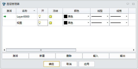
图5 图层管理器-创建视图
使用“图层管理器”(图6)创建“标注”图层,颜色为“暗蓝色”。
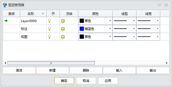
图6 图层管理器-创建标注
第六步:标注样式管理
在“属性”下拉菜单下进入“标注样式管理器”。把所有“标注”归属到“标注”图层下,如图7所示。
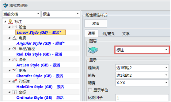
图7 样式管理器-标注图层
设置“线/箭头”和“文字”的颜色为“随层”,如图8所示。
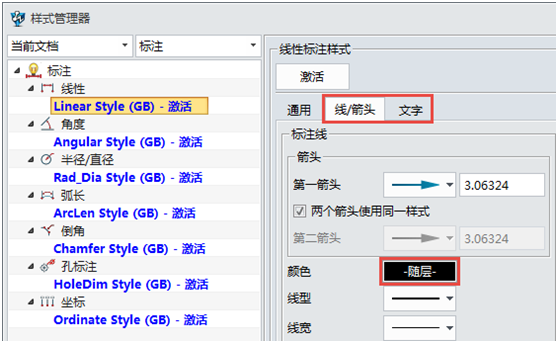
图8 样式管理器-随层设置
第七步:标注
切换到“标注”图层,对视图进行标注,如图9所示。
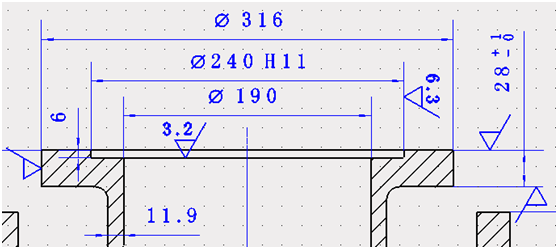
图9-1 标注1
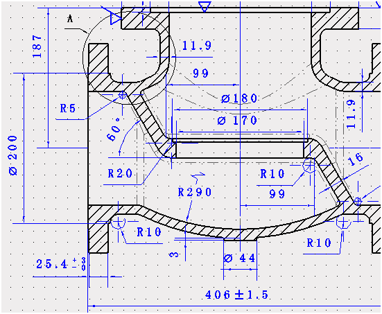
图9-2 标注2
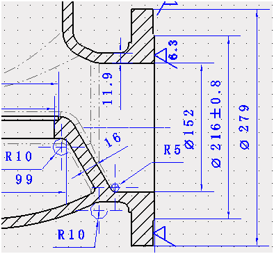
图9-3 标注3
第八步:局部视图
切换到“视图”图层,使用“布局”页面下的“局部”命令,创建局部剖视图,如图10所示。
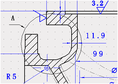
图10 局部剖视图
第九步:标注
切换到“标注”图层,对局部视图进行标注,如图11所示。
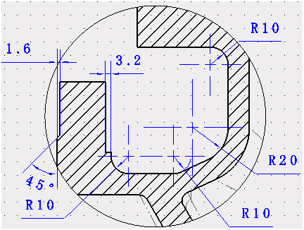
图11 标注
第十步:中心标记圆
使用“标注”页面下的“中心标记圆”命令,设置短线为“10mm”,如图12所示,图13为设置后的效果。

图12 设置
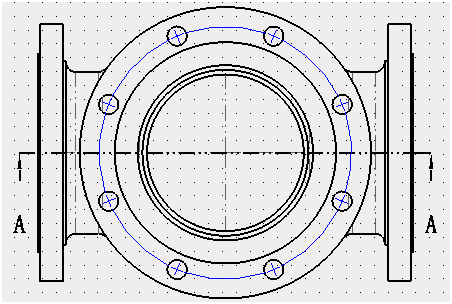
图13 中心标记圆
第十一步:标注
对视图进行标注,如图14所示。
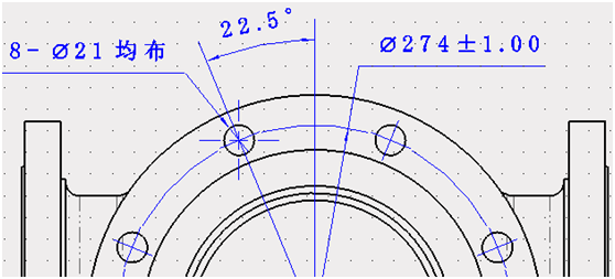
图14 标注
第十二步:中心标记
使用“标注”页面下的“中心标记”命令,设置短线为“5mm”,超出为“10mm”,如图15所示,完成后效果为图16。
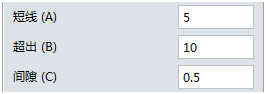
图15 设置
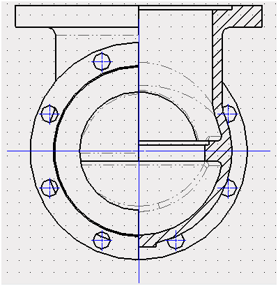
图16 中心标记
第十三步:中心圆标记
使用“标注”页面下的“中心标记圆”命令,设置短线为“10mm”,图17为设置,图18为完成后的效果。
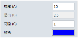
图17 设置
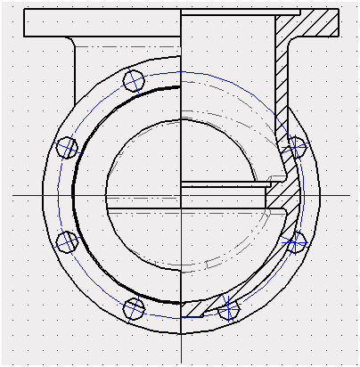
图18 中心圆标记
第十四步:标注
对视图进行标注,如图19所示。
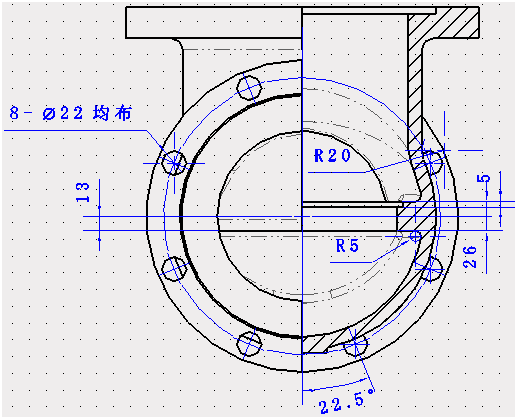
图19 标注
第十五步:生成DWG文件
在“文件”下拉菜单下,启动“在ZWCAD打开”命令,在弹出的“另存为”对话框里,点击确认,生成一个DWG文件,如图20所示。
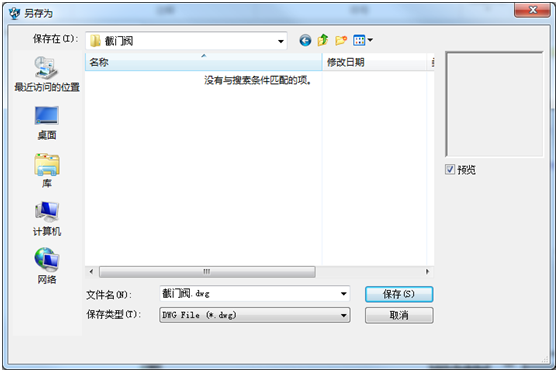
图20 另存为DWG
此时,如果你的电脑安装了中望CAD,会自动开启中望CAD软件(图21),如果使用其他CAD软件,也可手动打开中望3D另存为的DWG文件。
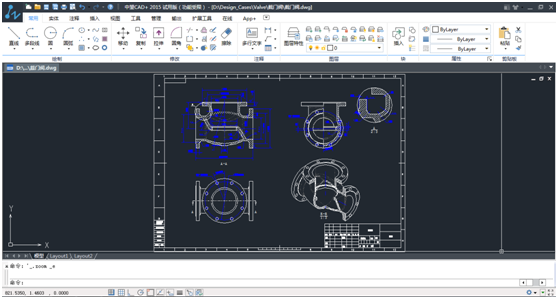
图21 中望CAD打开工程图
到此,阀体完整的工程图就完成导出了,能让设计师或者其他上下游对接的工程师清晰地掌握这个产品的各种详细信息,对工作效率的提升和产品质量的保障都是有极大帮助的。对于其他产品,设计师们也可以参照本文中工程图出图的步骤,完成对应的出图操作,并根据需要在CAD软件中打开及运用。
原文:https://www.zwcad.com/service_87_2282.html


 发表于 2016-10-31 15:21:05


 QQ好友和群
 QQ空间
QQ空间 腾讯微博
腾讯微博 腾讯朋友
腾讯朋友 收藏
收藏 淘帖
淘帖 赞一下!
赞一下!