2011-5-24 15:38| 查看: 74974| 评论: 2|原作者: 今明科技|来自: 今明科技
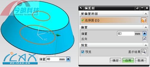
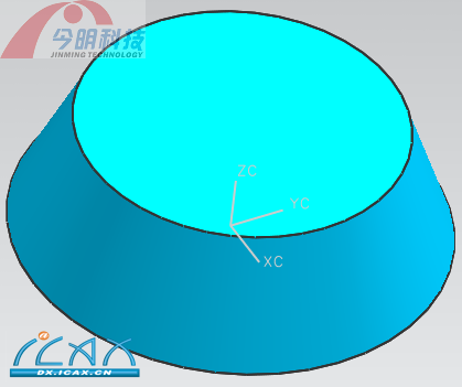
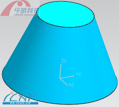
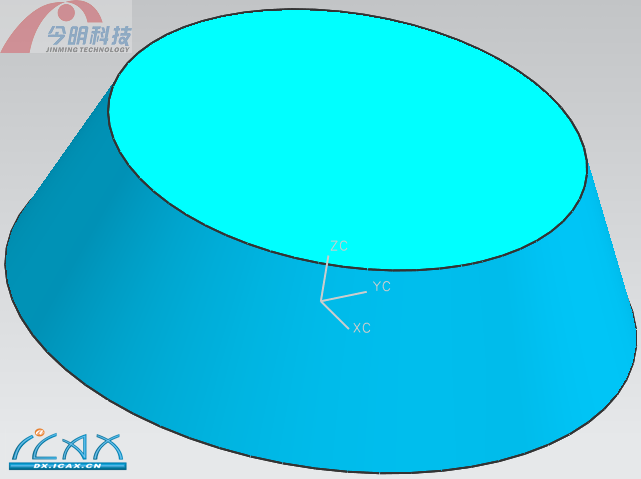
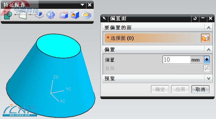
〖偏置面前实体〗
raywongh
elva3100
ty0917
dg3350576
jiangguirong369
yangzhiliccc
eyuhs
LKK52
wwuw
T15005703380
duola11
sylidb
yixiu090405
QQ 咨询|手机版|联系我们|iCAx开思网
GMT+8, 2025-4-5 00:38 , Processed in 0.017051 second(s), 12 queries , Gzip On, Redis On.
Powered by Discuz! X3.3
© 2002-2025 www.iCAx.org