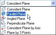
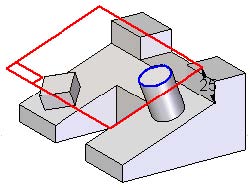
使局部平行平面垂直于窗口。在Draw(绘图)组中,选择Circle by Center(通过圆心画圆)命令。
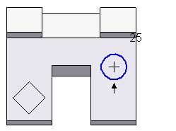
绘制如图所示的圆。不需要精确的尺寸和位置。
在工具条上选择Close Sketch(关闭草图)选项。

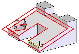
在命令栏上,点击Through Next(贯通下一个对象)拉伸选项并定位红色方向箭头,如图所示。
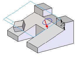
注意此时局部参考平面可见。在命令栏中点击Finish(完成)。
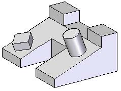
注意局部参考平面在特征创建模式外是不可见的。
第10步:最后演示的命令是参考平面Auto-Resize(自动调整尺寸)。这个命令能够根据草图/轮廓几何形状来调整局部参考平面的尺寸。
选择Select(选择)工具。

在PathFinder(路径查找器)中选择Protrusion(增料)特征。
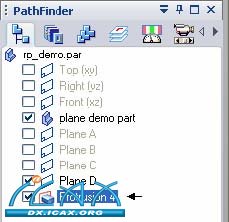
在命令栏中点击Edit Definition(编辑定义)。
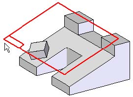
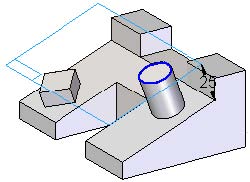
选择如图所示的局部参考平面。
注意参考平面的显示。出现了用于手动调整参考平面尺寸的句柄。自动调整平面尺寸。
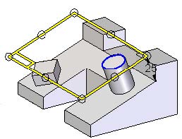
在命令栏中,选择Auto-Resize(自动调整尺寸)命令。注意局部参考平面是怎样根据轮廓/草图几何结构来调整的。
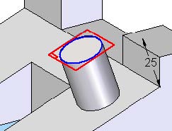
在命令栏中点击Finish(完成)。演示结束。
演示总结
演示展示了三类参考平面——基本、全局和局部。对参考平面类型的理解有助于您进行零件建模。当您有一定Solid Edge使用经验后,您将很容易决定应该使用哪种类型。