第二部分-模仁 设计 1. 创建工作零件—模仁(mold inserts). 基本操作顺序是: 型芯和行腔已经存在于模架中.在这里只是调整其尺寸. 然后将工作零件型面和分型面从分型子装配转移到工作零件(Mold inserts)中 使用分型面切割模仁镶件,然后缝合所有的面为封闭实体. 滑块的操作基本是一样的,但是这里必须先创建滑块镶件 先从调整型芯和行腔镶件尺寸入手. 模架尺寸通过设置参数(Setup Parameters)来控制的.使得模具的基本尺寸方便控 制.
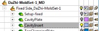
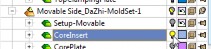
在装配树中显示型芯和行腔镶件
Open the Mold Setup tool from the Xelerated MoldDesign Guide 在模 具设计向导中打开模具设置(Mold Setup)工具
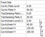
修改参数如下: CavityInsert Level (-) = 5 CavityInsert H = 45 CavityInsert X = 130 CavityInsert Y = 190
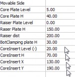
CoreInsert Level (-) = 20 CoreInsert H = 70 CoreInsert X = 130 CoreInsert Y = 190
Now we will transfer the active faces to the active parts 将分型面传送到工作零件 (active part) |