创建基于轮廓的特征(五)
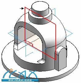
第9步:在零件上添加旋转的除料特征。为了创建该除料特征,需要加入并偏移一条现有的零件边缘。 选择Revolved Cut(旋转除料)命令 选择如图所示的参考平面。
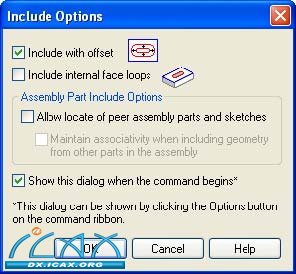
在Draw(绘图)组中,选择Include(包括)命令
在Include Options(加入选项)对话框中,设置Include with offset(包括并偏置),然后点击OK(确定)。
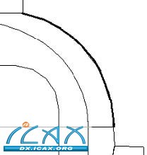
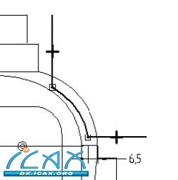
选择图示圆弧,然后点击命令栏上的Accept(确定)按钮。
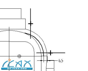
在Distance(距离)字段中输入6.5然后按回车键。
点击圆弧内侧以确认偏置。注意:系统在偏置元素与偏置起始圆弧之间添加了一个尺寸标注。
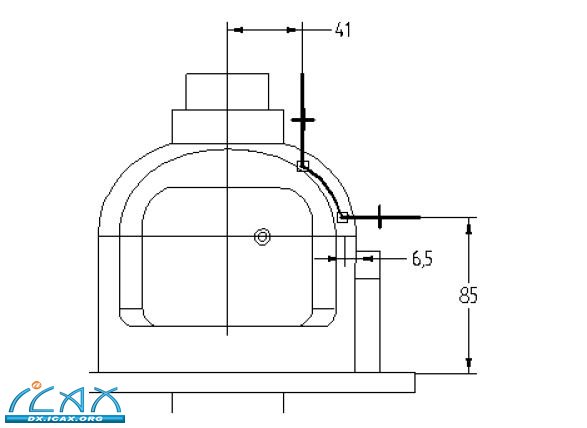
按照图示绘制一条水平线和一条垂直线。
选择Trim(修剪)命令
修剪线段和圆弧,产生以下轮廓形状。如果出现错误,点击主工具条上的Undo(撤销),然后重复该步骤。
选择Distance Between(距离)命令,按照图示添加尺寸标注。按照图示编辑尺寸标注值。
| 

