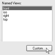
第4步:在新的图纸页上放置一个正视图。 在Sheet(图纸页)选项卡上右击并点击Insert(插入)以插入Sheet2。 点击Drawing View Wizard(图纸视图向导)命令。该对话框与第一次执行命令时显示的对话框不同,因为现在您已经放置了一个装配视图。 在Select Attachment(选择附件)对话框中点击OK(确定)。在Drawing View Creation Wizard(图纸视图创建向导)中,确保Configuration or PMI model view(配置或PMI 模型视图)字段中选择的是No selection(未选择)。点击Next(下一步)。 在Drawing View Orientation(图纸视图方向)对话框上点击Custom(自定义)选项。
在Custom Orientation(自定义方向)窗口中,按<Home> 键显示正等测视图。
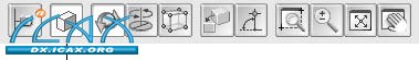
点击Shaded with VHL Overlay(使用VHL重叠着色)按钮。
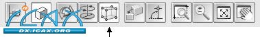
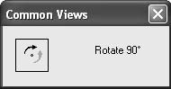
点击Common Views(公共视图)按钮。
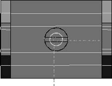
点击如图所示的Show face(显示面)视图。
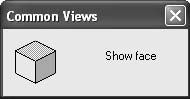
点击如图所示的Rotate 90° clockwise(顺时针旋转90度)。
点击右上角的X,关闭Common Views(公共视图)对话框。
下图显示了结果视图。
在Custom Orientation(自定义方向)窗口中的Close(关闭),然后在Drawing View Layout(图纸视图布局)页中点击Finish(完成)。
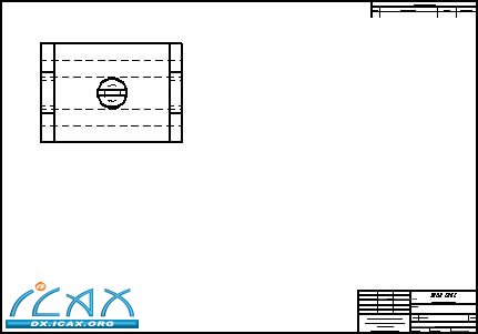
将比例改为1:1。
将视图放入图纸页的左上方区域。
第5步:在正视图上绘制一个用于创建剖视图的切割平面。
选择Cutting Plane(切割平面)命令。
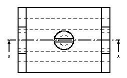
点击刚才放置的图纸视图,通过视图中心构造一条切割线。选择Close Cutting Plane(关闭切割平面)。切割平面类似于下图所示。
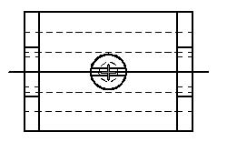
移动光标并点击切割平面的上侧,定义切割方向。
| 

